Why the attenuation requirement only fixes the LC product, why the optimum damping resistor isn't the characteristic impedance, and when a second filter section starts to pay for itself.
Two input filters. Same corner frequency, same 40dB of attenuation at the switching frequency, same damping network sized by the same rule. One has 26dB of stability margin. The other has none at all.
They differ in one thing: how the LC product was split. Filter A is 47µH and 0.22µF. Filter B is 2.2µH and 4.7µF. Multiply those out and you get the same number, so they corner at the same 49.5kHz and their attenuation curves lie exactly on top of each other. On the plot most of us look at when we design an input filter, they are the same filter.
Part 1 asked whether a filter you already have is stable, and worked through seven criteria that answer it. This article asks the question that comes first. What should the filter be?
The short answer is the useful one. Your attenuation requirement fixes the LC product and says nothing about the split. Your stability requirement fixes the inductor on its own. Pick the inductor from a catalogue and back out the capacitor, which is how most of us do it. You have fixed the product and left the ratio to chance.
The design: a 48V bus feeding a 200W buck
One converter throughout. A synchronous buck runs from a 48V distribution bus and delivers 12V at 16A, switching at 500kHz. It's the point-of-load end of the same 48V rail the boost converter article generates.
| Parameter | Value |
|---|---|
| Input bus | 48V |
| Output | 12V, 16A |
| Efficiency | 96%, so = 200W |
| Switching frequency | 500kHz |
| Attenuation needed at | 40dB |
| Stability margin | 6dB |
Inside its control bandwidth the converter holds output power constant, so its incremental input resistance is negative:
That is the number the filter has to stay clear of. Middlebrook's criterion says the filter's output impedance must sit well below the converter's input impedance at every frequency [1]. Aerospace and military specifications usually put a number on "well below", and 6dB is the common one [3]. So the filter's impedance peak has to stay under , which is 5.77Ω.
Note that 6dB is a factor of 1.995, not 2. The difference is small and I'll carry the exact figure, because the whole point of what follows is that the margin is tighter than it looks.
The attenuation requirement fixes the product, not the split
A single LC section rolls off at 40dB/decade, so an attenuation target at the switching frequency fixes the corner:
That fixes . It tells you nothing whatever about how the product is divided between them.
What the converter has to contend with is the filter's output impedance, and its peak scales with the characteristic impedance:
The second form is the one worth remembering. Once the attenuation requirement has fixed , the inductor alone sets the impedance peak. The capacitor is then whatever satisfies the corner. It has no say in the matter.
Fig. 1 shows what that costs in practice. Both filters carry an – damping branch sized the same way, and both are optimally damped, which I'll come back to. Filter A peaks at 12.7Ω, straight through the converter's 11.5Ω. Filter B peaks at 0.59Ω and clears it by 26dB.
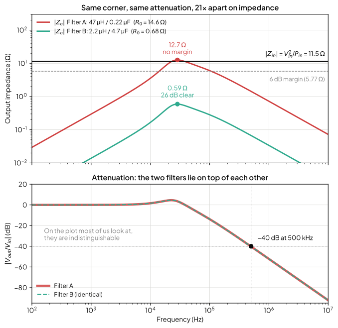
The bottom panel is the part that should worry you. Those two curves aren't merely similar. They're the same curve. Scaling every impedance in a network by the same factor leaves the transfer function untouched. No amount of staring at an attenuation plot will separate a filter that works from one that doesn't.
Sizing the inductor from the margin
If the inductor sets the peak, size the inductor from the margin and let the capacitor follow. Written out, with the peak impedance you're allowed:
is the damping factor, and it depends on how much damping capacitance you fit. For the standard – branch with , optimally damped, [2]. At the usual = 4 that's 0.866.
For this converter, = 5.77Ω and = 50kHz, so the inductor has to come in under 21.2µH, and the capacitor is then 0.477µF. Fig. 2 is the same statement as a picture. Because the peak is , it's a straight line on log axes, and the design question reduces to which side of a vertical line you're on.
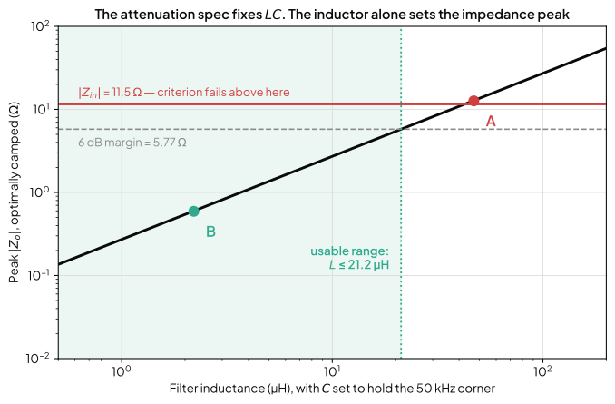
47µH was never going to work here. Not because it's a bad inductor, but because at a 50kHz corner it implies a 14.6Ω characteristic impedance against a converter that presents 11.5Ω. That was decided the moment the inductor was chosen, before anything was damped.
The damping resistor isn't the characteristic impedance
Here's where the standard advice stops being good enough, and I've published the standard advice myself.
The rule of thumb is and . The first half is fine. The second is a decent approximation that gets steadily worse as the damping capacitor grows, and the exact result is not hard to use. For , the resistance that minimises the impedance peak is [2]:
At = 4 that's , not . Filter B's optimum is 0.42Ω against a characteristic impedance of 0.68Ω.
Fig. 3 puts the three standard damping networks on one axis, each at its own optimum, so you can see what each one can actually buy you.
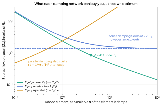
That figure settles a choice that the placement comparison made on other grounds. Use the – branch across the filter capacitor unless capacitance is genuinely constrained. It's the only one of the three that keeps improving without limit as you spend, and past = 2 it drops below the floor that series damping can never get under.
Why a bigger damping capacitor can't rescue a bad split
When the margin comes up short, the instinct is to fit a bigger electrolytic. If you have already chosen the damping resistor and left it alone, that doesn't work, and the reason is worth understanding rather than memorising.
Let grow without limit. The blocking capacitor becomes a short circuit at the resonance, so the damping branch becomes connected straight across the tank, and the impedance peak tends to itself. With set to , the peak can never fall below , no matter how much capacitance you fit. The optimum has no such floor. It keeps falling as .
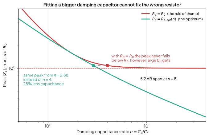
The practical reading is the horizontal one. At = 4 the rule of thumb gives . The correct resistor reaches that same peak at = 2.88, which is 28% less damping capacitance for an identical result. Fitting more capacitance with the wrong resistor is worse than fitting less with the right one, which is exactly backwards from how the rule gets used.
One exception, and it works in your favour. All of that assumes is a value you chose and then left alone. Plenty of designs fit no resistor at all and let an aluminium electrolytic's ESR do the damping, which is a sound trick and one I've recommended myself. Adding capacitance then lowers the resistance as well, because ESR falls roughly as inside a capacitor family. Quadruple filter B's damping branch, from 18.8µF to 75.2µF. With a fixed resistor the peak barely moves, from to . With the ESR coming down as the capacitance goes up it reaches , within 3% of the true optimum. So the reflex is right when ESR is doing the damping and wrong when a resistor is. Find out which one you have before you buy a bigger part.
None of that saves filter A. To reach the 0.59Ω that filter B gets from 18.8µF of damping capacitance, filter A needs = 1219. That is 268µF, across a 0.22µF filter capacitor. The branch has to be enormous compared to a capacitor that was tiny to begin with. A bad L/C split gets paid for in electrolytics, and the bill is not reasonable.
Two sections, and when the second one pays
The single-section argument has a floor of its own. Pushing down to win impedance margin forces up to hold the corner, and eventually the capacitor is the expensive part instead of the inductor. Two cascaded sections break that trade, because four poles give 80dB/decade and the corner can sit much closer to the switching frequency.
The usual claim is that two sections are smaller. For this converter, they're barely smaller at all.
| Corner | Per section | Total | Total | Stored energy | |
|---|---|---|---|---|---|
| One section | 50.3kHz | 21.1µH, 0.475µF | 21.1µH | 2.37µF | 2918µJ |
| Two sections | 161.8kHz | 4.7µH, 0.207µF | 9.4µH | 2.07µF | 2466µJ |
Both designs meet 40dB at 500kHz and both hold the impedance peak at 5.77Ω. Splitting into two sections more than halves the inductance. But the total capacitance hardly moves, and on a 48V rail the term dominates everything. The saving is 15%.
Sweep the attenuation requirement and the picture makes sense (Fig. 5).
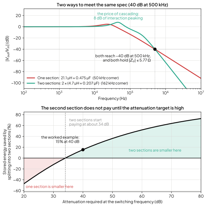
Below about 34dB the second section makes the filter bigger, not smaller. The advantage only becomes decisive past 50dB, where it reaches 36%, and past 60dB, where it reaches 52%. Erickson's own two-stage example needs 80dB at 250kHz, and there the difference is enormous. His single section takes 330µH and 1670µF of capacitance including damping. His two-section design takes 55.5µH and 18.6µF [2]. Part of that fall in capacitance is topology rather than cascading, because he damps the two-section filter with inductors instead of capacitors.
So the honest guidance is not "use two sections". It's that the second section costs you until the attenuation requirement is high enough, and for a 48V rail the crossover sits around 34dB. Below that, one section and a well-chosen ratio wins.
Two things go with that. The sections interact, and here that costs 8dB of passband peaking against 4.6dB for the single section. Both sections above are also identical, which is the simplest comparison rather than the best design. Stagger-tuning the two corners would cut the peaking and probably move the break-even down.
There's also a stability rule for the second section, and it should look familiar. Adding a section doesn't disturb the first section's output impedance, provided the new section's driving impedance stays low enough. It has to sit below the first section's input impedance, measured with its output both shorted and open [2]. That's Middlebrook's criterion again, applied one level further back.
How to size an input filter, start to finish
Six steps, in this order:
- Get the attenuation requirement. How much help do the conducted emissions need at the switching frequency? Call it .
- Corner frequency from the attenuation. for one section. This fixes and nothing else.
- Converter input impedance. , and divide by your margin. At 6dB, .
- Inductor from the margin. , with and = 4 for a start. This is the step that usually gets done backwards.
- Capacitor from the corner. . It's not a free choice.
- Damping resistor from , not from . , and .
Then check the result. If step 4 gives an inductance you can't buy or can't fit, the fix is a second section or a lower attenuation target, and not a larger damping capacitor.
Sometimes the filter is already on the board, and you need to damp it rather than resize it. Input Filter Damping: Sizing Rd and Cd to an Impedance Target covers that case. It picks the smallest damping capacitor that reaches your margin, and works out what the resistor dissipates.
Where this leaves you
The thing I'd change about how most of us design input filters is the order. The corner frequency comes from the emissions requirement, and almost everybody gets that right. The split gets decided by whatever inductor is already in the library, and that's the decision that determines whether the converter is stable.
That ordering problem is exactly the sort of thing a design tool should catch before it reaches hardware, which is why switchmode.io is built around impedance margins rather than component checklists. The input filter calculator takes the rail, the switching frequency and an attenuation target, then sizes the filter and its damping network. It reports next to the Middlebrook and GMPM margins it achieved. There's a check mode too, for a filter you already have. That's the quick way to find out whether the one in your current design is filter A or filter B.
References
[1] R. D. Middlebrook, "Input filter considerations in design and application of switching regulators," in Proc. IEEE Ind. Appl. Soc. Annu. Meeting, 1976, pp. 366-382. [Online]. Available: https://ridleyengineering.com/images/pdf/Middlebrook1976BritishLibrary.pdf
[2] R. W. Erickson and D. Maksimović, Fundamentals of Power Electronics, 3rd ed., Springer, 2020. Ch. 17 (input filter design and damping networks).
[3] SynQor, "Input system instability," Application Note Doc# 065-0000060. [Online]. Available: https://www.synqor.com/document-download?document=Input+System+Instability.pdf