Where the 30% rule comes from, why the optimum is a basin rather than a number, and why no two manufacturers' saturation ratings mean the same thing.
Almost every buck design starts the inductor the same way: pick 30% ripple, solve for , round to the nearest standard value, check the saturation rating has some margin, move on. It is a good rule and it has been the default for twenty-five years. It comes from a real optimisation rather than from folklore.
But three things about it are worth knowing before you rely on it. The first is that the optimum it targets is extremely flat with anywhere from about 0.25 to 0.5 costing you almost nothing, so the precision implied by "30%" is fictitious. The second is that the ripple ratio is not a property of your design at all; it is a property of an operating point, and it moves as soon as the input voltage or the load does. The third is that the saturation current you check it against is defined differently by every manufacturer, with a spread wide enough to reverse a part selection.
This article works through all three on one converter. If you want to run the numbers for your own design as you read, the buck inductor calculator computes everything below.
The design: 12V to 1.8V, 20A at 500kHz
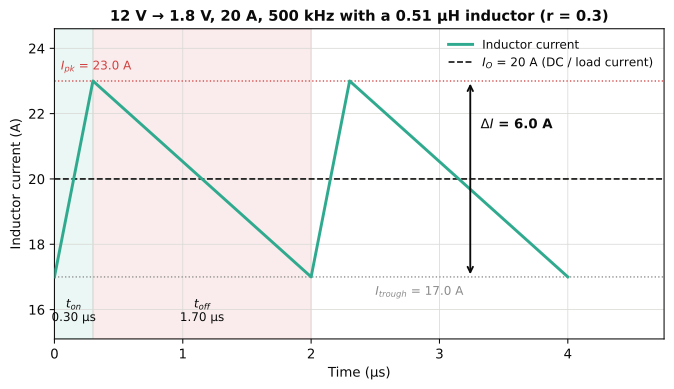
The example is the same point-of-load converter used in the MOSFET selection article: a server or FPGA rail at = 12V, = 1.8V, 20A maximum load, 500kHz switching. The duty cycle is:
So the high-side switch is on for 0.30µs and off for 1.70µs. During that off-time the inductor has across it, and the volt-seconds it must absorb are fixed by the specification alone:
That number is the whole design constraint and nothing you choose changes it. What you choose is how to split it between current and inductance, because .
Ripple ratio is the actual design variable
Rather than working in amps, the design collapses to one dimensionless number: the current ripple ratio, defined as the AC component divided by the DC component at maximum load [3].
For our converter, choosing = 0.3 gives = 6.0A and therefore:
The peak current follows immediately, and it is the number that decides whether the core saturates:
The RMS current, which decides how hot it gets, barely moves:
Take a closer look at that last one. At = 0.3 the RMS current is 0.4% above the DC current, even at = 0.6 it is only 1.1% above. Across the entire practical range of ripple ratios the RMS current is, for copper-loss purposes, just the load current [3]. That is convenient, and it also means RMS current tells you nothing useful about whether your ripple choice was good.
Where the 30% rule comes from, and what it costs elsewhere
The rule traces back to TI/National's AN-1197 [3], which derives it from the inductor's energy handling requirement which is the quantity that actually sets physical size:
Since and are fixed by the specification, only the bracketed term varies. It falls steeply as increases from zero, then flattens out. The knee is at 20–40%, and that knee is the entire basis of the rule.
The reason not to keep going past the knee is that everything downstream gets worse. The output capacitor RMS current is , directly proportional to . Going from = 0.3 to = 0.6 shrinks the inductor's energy requirement by about 36%, but doubles the output capacitor's RMS current and therefore quadruples its dissipation [3]. You have traded a smaller inductor for an output capacitor with twice the ripple-current rating.
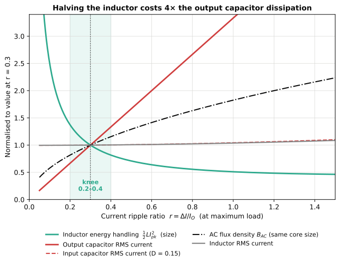
Two of those curves are worth a comment.
AC flux density rises as . Reducing reduces the flux swing for a given current swing, but is rising at the same time, and if you keep the same core you achieve the lower inductance with fewer turns. Since and , the net result is [3]. Core loss follows with typically 2.2–2.6, so core loss climbs meaningfully even before you consider going to a smaller core.
Input capacitor RMS current barely responds to at this duty cycle. At = 0.15 it is dominated by the term which is about 7.2A, four times the output capacitor's 1.7A. At higher duty cycles the dependence becomes much stronger, which is why AN-1197 plots it against duty cycle and warns about the cost penalty on the input capacitor [3]. For low-duty point-of-load designs the input capacitor is a big problem, but not one that your ripple choice makes much worse. The switch RMS currents behave the same way; see the MOSFET selection article for what those do to conduction loss.
The loss optimum is a basin, not a point
Energy handling is a proxy for size. If what you actually care about is efficiency, the trade is between DC copper loss and core loss, and it runs the other way.
Within one package family, DCR scales roughly with inductance with TI noting that in the same form factor a 1µH part has about twice the DCR of a 0.56µH part [1]. So more inductance means lower ripple but more copper resistance, while less inductance means less copper but higher flux swing and more core loss. Taking for a 20A-class part and = 2.3:
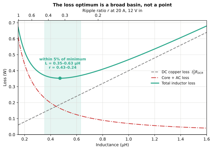
The minimum is at 0.47µH, corresponding to = 0.32. But the curve either side of it is nearly flat: anything from 0.35µH to 0.63µH is within 5% of optimal, which is a ripple ratio anywhere between 0.24 and 0.43. TI's own measurements show the same thing over an even wider span, with total loss essentially flat from = 0.2 to 0.6 [1].
This is the most useful thing to take from the rule. The answer is not 30%. The answer is that the objective function is flat over a factor of two in inductance, so you should spend your effort on the constraints that are not flat such as saturation margin, temperature rise, and what the part costs, then simply take whichever standard value in that range is best on those. Richtek reach the same conclusion from an independent area-product derivation, and land on an optimum nearer 0.42–0.48 for their example [4]; the disagreement with 0.3 is real but it does not matter, because both sit inside the basin.
The ripple ratio is not a property of your design
is defined at one operating point: maximum load, at one input voltage. Notably, your converter does not stay there all the time.
Rearranging, the inductance needed to hold = 0.3 is:
which is a function of . Over a 6–18V input range that is 0.42µH at low line and 0.54µH at high line equating to a 29% spread. You obviously cannot fit all of them. You fit one inductor, and then becomes whatever the operating point makes it.
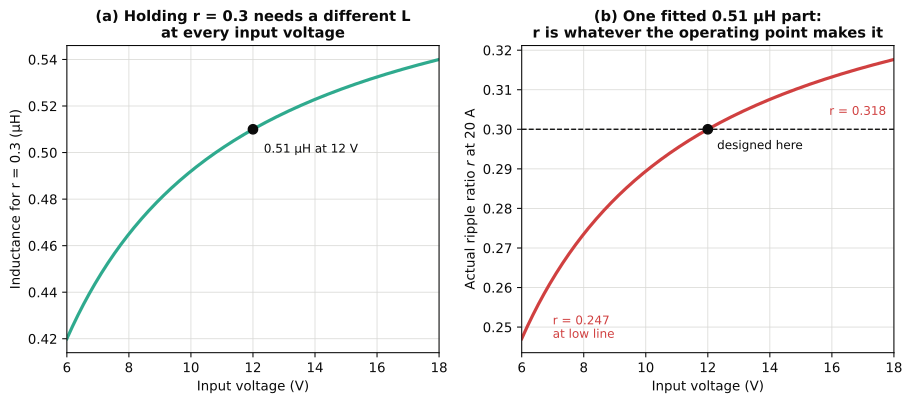
For this design the consequence is mild with wandering from 0.247 to 0.318, comfortably inside the basin from Fig. 3, which is another way of saying the design is insensitive. For a wide-input converter it is not mild at all, and the right approach is to check the extremes rather than the nominal:
- Peak current, and therefore saturation, is worst at maximum input voltage and maximum load. High line gives the largest .
- DCM onset is worst at maximum input voltage and minimum load, for the same reason.
- Core loss is worst at maximum input voltage, since tracks .
Specify at nominal if you like, but verify at the corners. The same logic applies to the component values themselves with inductance carrying a ±20% tolerance before DC current bias and temperature are even considered. The worst-case phase margin article works through what that does to a compensated loop.
The CCM/DCM boundary sits exactly at r = 2
There is one value of that is not a preference but a boundary. As load falls at fixed input voltage, stays constant while the DC level drops, so rises. When the trough of the triangle reaches zero the inductor current becomes discontinuous. That happens when , which is exactly [3][4].
The load at which it happens follows directly. If a design has ripple ratio at full load , it enters DCM at:
For our converter, at 15% of full load.
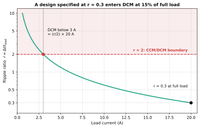
That 15% figure is a design output, not a footnote. Below it, three things change at once. The plant transfer function loses its LC double pole and becomes essentially first-order, which changes the loop you compensated. See the compensator design article for what the double pole was doing in the first place. The conversion ratio stops being and becomes load-dependent. And if the converter is a synchronous design running forced-PWM, it does not enter DCM at all; it circulates negative inductor current instead, trading light-load efficiency for a plant model that stays put.
Choosing a larger inductor to keep CCM down to a lower load is a legitimate reason to move away from the loss optimum. It is one of the few.
Now read the datasheet: two current ratings that mean less than they look
Every power inductor datasheet gives two current ratings, and they answer two different questions [2]. addresses core saturation from the peak current. addresses self-heating from the RMS current. You must check both, against = 23.0A and = 20.07A respectively.
The problem is what those two numbers actually mean.
Saturation: the same part, many different ratings
is the DC bias at which inductance has fallen by a specified amount from its zero-bias value. The specified amount is not standardised. Vishay rate the IHLP series at a 20% drop and note plainly that some manufacturers rate at 30%, which makes a part "appear to have better saturation" [5]. TI describe the typical definition as inductance declining to 70% of nominal equating to a 30% drop [1]. Coilcraft's selection guide says definitions in the range of 10–20% are common but that some catalogues use 50% [2], while the example part in that same document is specified at 30%.
So the range in active use runs from 10% to 50%. Reading off a comparison table without reading the footnote is not a comparison at all.
How much this matters depends on the core, and that is the second thing the number hides. Ferrite drum cores saturate hard: inductance holds flat and then collapses at a knee. Powder and composite cores saturate soft, rolling off gradually from low current with no knee at all [5].
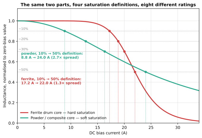
For the ferrite, the four definitions are within 30% of each other so the knee is sharp enough that it hardly matters which you use. For the powder core the same four definitions give ratings a factor of 2.7 apart. The choice of definition matters most exactly where the part is most forgiving, which is also where a vendor has the most to gain from choosing a generous one.
That leads to opposite design rules for the two materials:
- Hard-saturating (ferrite). Keep below the rating with real margin. Past the knee, inductance collapses, runs away, and the current can rise uncontrollably within a single switching cycle [5]. There is no graceful degradation.
- Soft-saturating (powder/composite). Running peaks near or slightly beyond the quoted rating is often acceptable, and Coilcraft point out that it is desirable to operate with peaks near the saturation rating because that is what lets you use the smallest part [2]. What you lose is inductance, which raises ripple, which raises peak current further meaning you need to check where it settles rather than assuming.
Also note that inductance itself is a small-signal number, measured at 100kHz–1MHz with about 0.1Vrms applied and no DC bias [2]. It is not the large-signal inductance your converter sees at 20A. This is the same class of error as reading off the front page of a MOSFET datasheet: a curve, sampled at one convenient point, presented as a constant.
RMS current: a 40°C rise, measured with DC
is the continuous current producing a specified temperature rise of which the standard is 40°C for power inductors and 15°C for chip inductors [1][2]. Two things about it are routinely missed.
First, the rise is on top of ambient, in still air, on the manufacturer's test board. An inductor sitting next to a hot MOSFET on a dense board has a different thermal environment than the one the rating was measured in.
Second, and more importantly, the rating is measured with DC or low-frequency AC [2]. It captures and nothing else. It does not include core loss, and it does not include the AC winding resistance from skin and proximity effects. Coilcraft's own guidance is that AC resistance is not comparable to DC resistance below about 200kHz, but that above 200–300kHz you should ask the supplier for loss-versus-frequency data, because it is not on the datasheet [2]. Our converter runs at 500kHz.
And the DCR you are checking against is specified at 25°C. Copper's temperature coefficient is about +0.4%/°C, so a part rated 0.51mΩ at 25°C is 0.63mΩ at 85°C equating to a 24% greater copper loss than the datasheet number [2]. The hidden losses article covers the AC winding mechanisms and the temperature dependence in more detail.
What the datasheet won't tell you: core loss under triangular flux
The final gap is the core-loss curve. When a manufacturer publishes one, it is almost always characterised under sinusoidal excitation, because that is the repeatable instrument condition. Your buck inductor sees a triangular flux waveform with a duty-cycle asymmetry meaning 15% up and 85% down in this design.
The classical Steinmetz equation,
is only valid for sinusoidal excitation [7]. Applying it to a rectangular-drive waveform is an extrapolation, and at extreme duty cycles it is not a small one. The standard fix is the improved generalised Steinmetz equation (iGSE) [6], which handles arbitrary waveforms using the same three Steinmetz parameters:
with derived from , and . Later work extends this again to account for relaxation losses during the zero-voltage intervals that rectangular drive produces, which the iGSE assumes are lossless [7].
The practical consequence for selection is modest but worth knowing: a datasheet core-loss figure read at your switching frequency and flux swing is an estimate whose error grows as the duty cycle moves away from 50%. At = 0.15 you are a long way from 50%. If core loss is a significant fraction of your budget, which Fig. 3 says it is below about 0.4µH, this is worth checking against the manufacturer's own loss calculator rather than a hand-applied Steinmetz fit.
Putting it together
For the worked example, the selection reduces to a short list of checks:
| Quantity | Value | What it constrains |
|---|---|---|
| Volt-seconds | 3.06 V·µs | Fixed by the specification |
| Target | 0.35–0.63 µH | Within 5% of the loss optimum |
| , worst case | 23.2 A at 18V (23.0 A at 12V) | , read with its footnote |
| 20.1 A | rating, derated for ambient and frequency | |
| DCM onset | 3.0 A, 15% of full load | Light-load behaviour and the loop model |
| over 6–18V | 0.247 – 0.318 | Stays inside the basin: design is insensitive |
Pick a standard value in the range, check the peak against a saturation rating whose definition you have actually read, check the RMS against a thermal rating you have derated for your board and your switching frequency, and confirm where DCM starts. The ripple ratio was never the answer just a convenient way to parameterise the search.
Doing this properly means carrying each of those checks at the operating corner where it is worst rather than at nominal, with the inductor's real versus DC-bias curve rather than its headline value, and with core loss computed for the actual triangular flux waveform rather than read off a sinusoidal curve. Holding the whole design at its worst-case corners simultaneously, with real characterisation data extracted from manufacturer datasheets instead of typical values, is exactly the analysis switchmode.io is being built to do. The buck inductor calculator is the first piece of it, and it will run every number in this article for your own design.
References
[1] M. Jacob, "Select inductors for buck converters to get optimum efficiency and reliability," Texas Instruments Analog Design Journal, SLYT775, 3Q 2019. [Online]. Available: https://www.ti.com/lit/pdf/slyt775
[2] L. Crane, "Selecting the Best Inductor for Your DC-DC Converter," Coilcraft, Document 469, rev. 2017. [Online]. Available: https://www.coilcraft.com/en-us/resources/application-notes/selecting-the-best-inductor-for-your-dc-dc-convert/
[3] Texas Instruments, "AN-1197 Selecting Inductors for Buck Converters," SNVA038B, May 2001, rev. April 2013. [Online]. Available: https://www.ti.com/lit/an/snva038b/snva038b.pdf
[4] E. Wang, "Current Ripple Factor of a Buck Converter," Richtek Technology, Application Note AN009, April 2014. [Online]. Available: https://www.richtek.com/Design%20Support/Technical%20Document/AN009
[5] Vishay, "Inductor Saturation Current — Did You Know?," VMN-MS7373, 2017. [Online]. Available: https://www.vishay.com/docs/48155/_did-you-know_ihlp_saturation_vmn-ms7373.pdf
[6] K. Venkatachalam, C. R. Sullivan, T. Abdallah and H. Tacca, "Accurate prediction of ferrite core loss with nonsinusoidal waveforms using only Steinmetz parameters," IEEE Workshop on Computers in Power Electronics (COMPEL), 2002, pp. 36–41.
[7] J. Mühlethaler, J. Biela, J. W. Kolar and A. Ecklebe, "Improved Core-Loss Calculation for Magnetic Components Employed in Power Electronic Systems," IEEE Transactions on Power Electronics, vol. 27, no. 2, pp. 964–973, Feb. 2012.
[8] R. W. Erickson and D. Maksimović, Fundamentals of Power Electronics, 3rd ed., Springer, 2020.