A Class II ceramic capacitor loses capacitance under DC bias, and the loss isn't set by how close you run it to its rating. This note estimates what's left from four things on the datasheet's first page: the marked capacitance, the dimensions, the dielectric code and your voltage. Then it corrects for the small ripple a converter actually puts across the part, and for temperature. The constants come from 20,947 parts' bias curves, taken from Murata's, KEMET's and KYOCERA AVX's own tools. The worked example is the output capacitor of the 48 V to 12 V, 500 kHz buck from Dead Time in a Synchronous Buck: Choosing Both Edges from the Datasheet.
Use it before you've chosen a part, to pick a case and a part count. Once you've chosen one, read the vendor's own curve for it.
The result
- The loss follows the field in the dielectric layers, and the label gives you that field. Take the voltage times the square root of capacitance per unit volume. It predicts the loss about four times better than the applied voltage as a fraction of rated. On X7R parts the fit wasn't trained on, it lands within 7.4 points of the vendor's curve for four readings in five.
- Density splits the parts into two groups. Above about 1 µF/mm³, a part reads about 24% below its marked value at a converter's ripple level, before any bias is applied. At −40 °C it loses a further 18%. Below that density, both effects are small. The temperature code doesn't predict either.
- Three rules of thumb fail on the data. Running at half the rated voltage doesn't protect the capacitance. A higher voltage rating in the same case usually buys nothing. X7R doesn't reliably lose less than X5R. A bigger case does help, but only when everything else is held the same.
In the worked example, seven 22 µF 1210 parts are needed where the label suggests three and the vendor's 25 °C curve suggests four.
Why the label predicts the loss
A multilayer capacitor is a stack of dielectric layers, each of thickness and overlap area . Its capacitance is , and its active volume is about . Eliminate and the layer thickness is
where is the permittivity of free space, is the dielectric's relative permittivity, is the active volume and is the capacitance. The field in each layer is the voltage over the thickness. Let the package volume stand in for the active volume, and leave out the constants. That gives a field proxy you can read off the datasheet:
where:
- is the field proxy, in V·√(µF/mm³).
- is the DC voltage across the capacitor, in V.
- is the marked capacitance, in µF.
- is the package volume, length × width × thickness, in mm³.
The ferroelectric material responds to the field, not to the voltage rating. So two parts at the same should lose about the same share, whatever their case, rating or vendor. Fig. 1 tests that on the 1,764 X7R parts of 100 nF and above whose height the catalogue holds.
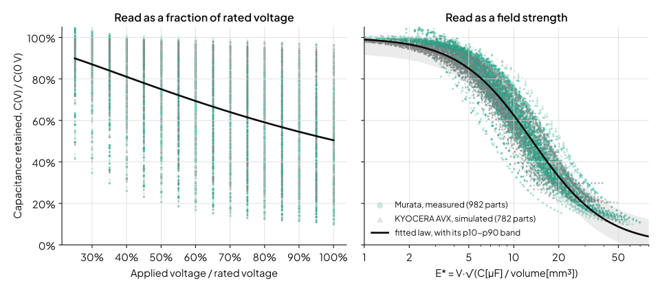
Against the fraction of rated voltage, the rank correlation with the retained capacitance is −0.52. Against it's −0.97. Fitted separately on all their X7R parts, Murata's measured curves and AVX's simulated ones put within 1% of each other. The catalogue holds no heights for KEMET's parts, so they can't go on this plot. Use footprint area in place of volume, and KEMET's medians fall within 7 points of the other two vendors' in every bin.
Earlier work says density matters. KEMET's high-reliability catalogue says stability "is related inversely to the packaging efficiency" [1]. Novak found a thinner part of the same footprint lost more [2]. Würth fits one part's curve from that part's own data [3]. Jiang et al. infer the dielectric thickness from a measured curve [4], which runs the opposite way. I haven't found a source that predicts one part's loss from its label.
What you need
From the datasheet's first page:
- The marked capacitance .
- The length, width and thickness, nominal values in mm. Use the thickness for your exact part number, because one case size comes in several heights.
- The dielectric code: X7R, X5R, X6S, X7S or X7T.
From the design: the DC voltage across the capacitor, and the temperature range it works over.
Step 1 Work out the field proxy and the density
where:
- is the field proxy, in V·√(µF/mm³).
- is the capacitance density, in µF/mm³.
- is the DC voltage across the capacitor, in V.
- is the marked capacitance, in µF.
- is length × width × thickness, in mm³.
Step 2 Read the bias retention from the law
where:
- is the capacitance at bias over the capacitance at 0 V, both at 25 °C.
- is the field proxy from Step 1.
- is the field at which the part keeps half its capacitance, from the table.
- is the steepness, from the table.
| Dielectric | Error, p50 | p80 | p90 | Same law on V/V_rated, p80 | ||
|---|---|---|---|---|---|---|
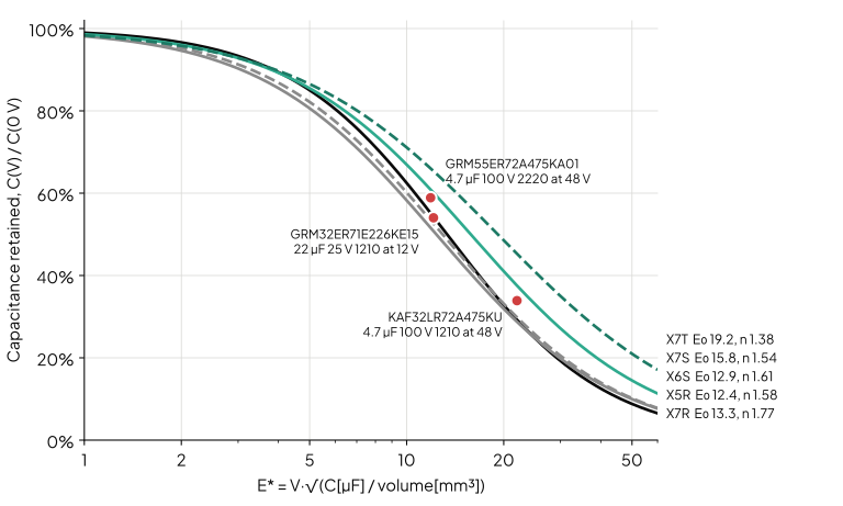
| X7R | 13.34 | 1.77 | 0.035 | 0.074 | 0.100 | 0.288 |
| X5R | 12.36 | 1.58 | 0.054 | 0.101 | 0.136 | 0.294 |
| X6S | 12.92 | 1.61 | 0.053 | 0.096 | 0.128 | 0.238 |
| X7S | 15.81 | 1.54 | 0.033 | 0.081 | 0.101 | 0.274 |
| X7T | 19.17 | 1.38 | 0.054 | 0.094 | 0.115 | 0.235 |
The constants were fitted on a random 80% of the parts of 100 nF and above, between 25% and 100% of rated voltage. The errors are absolute differences from each part's own curve, on the other 20%. That's 353 X7R parts and 46 to 136 parts of the others. The error on the held-out parts matches the error on the fitted ones, so two constants per dielectric aren't overfitting. The X7R error is the same for both vendors: 0.073 at p80 for Murata and 0.074 for AVX. The other four dielectrics come from Murata alone.
Fig. 2 plots the five laws, so you can read straight off it.
Step 3 Correct for the ripple level
A datasheet marks the capacitance at 0.5 Vrms or 1 Vrms. Converter ripple across an output capacitor is closer to 10 mV, and a Class II dielectric reads lower at a small AC level. Murata's SimSurfing publishes its bias curves at 0.01 Vrms [5]. So the 0 V point of each curve, over the marked value, measures this factor:
where:
- is the capacitance at your voltage, at 25 °C, at a ripple level of about 10 mV.
- is the small-signal factor from the table.
- is the retention from Step 2.
- is the marked capacitance.
| Density | Parts | , median | p10 to p90 |
|---|---|---|---|
| below 1 µF/mm³ | 738 | 0.96 | 0.73 to 1.01 |
| 1 µF/mm³ and above | 1,270 | 0.76 | 0.65 to 0.86 |
The split is by density, not by dielectric code. Dense X7R parts read a median 0.69 of marked, lower than the dense X5R parts' 0.77. Fig. 3 shows the two groups. Between 0.3 and 1 µF/mm³ they overlap, and 31% of those parts read below 0.85. If your part is there and the margin matters, take 0.76.
The size of the effect agrees with the published measurements. EPCI gives an "additional -5 to -15%" at 10 mV [6]. Novak gives "0 … -20%, sometimes up to -30%" [7], and Samsung Electro-Mechanics up to 30% near zero bias [8]. The table comes from Murata's curves only. KEMET and AVX don't state the AC level behind their curves. Both normalise them to 0 V, so the factor can't be read from them.
An input capacitor carries more ripple than an output capacitor, often a few hundred millivolts. Its factor sits between and 1. Most input capacitors at 48 V are below 1 µF/mm³ anyway, where the factor is close to 1.
Step 4 Correct for temperature
Read the temperature factor at bias, not the datasheet's temperature curve. That curve is measured at 0 V and at the large marking signal, and it says the wrong thing about a dense part.
where:
- is the effective capacitance at your voltage and temperature.
- is the capacitance at bias and temperature over the capacitance at the same bias and 25 °C, from the table.
- is the capacitance from Step 3.
| Density | −40 °C | 85 °C | 105 °C | 125 °C |
|---|---|---|---|---|
| below 1 µF/mm³ | 0.95 | 0.92 | 0.88 | 0.84 |
| 1 µF/mm³ and above | 0.82 | 1.05 | 1.02 | 0.97 |
The values are medians at half rated voltage, from 1,855 Murata parts of 1 µF and above that publish their bias curve at each temperature. Interpolate in temperature between columns. The spread is wide: at 85 °C the dense parts run from 0.92 to 1.16 at p10 and p90. Low-density parts behave as the temperature code suggests, losing capacitance hot. Dense parts gain a little up to about 85 °C and lose 18% at −40 °C, which makes cold the worst case for them.
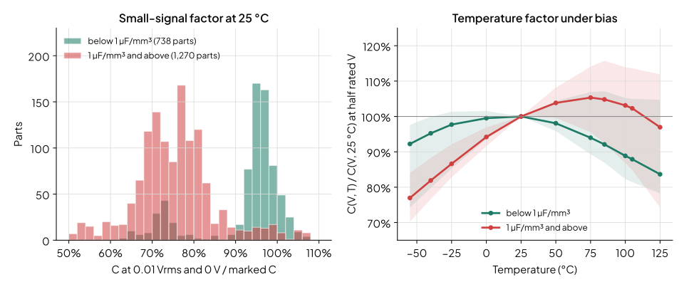
Don't multiply the 0 V temperature factor by the 25 °C bias factor. Against the measured families, that product is 6% optimistic at 85 °C and 8% optimistic at 125 °C, in the median. Novak found that bias and temperature were independent from −5 °C to 70 °C on one part [2]. Over that range the catalogue agrees.
Step 5 Run it backwards to choose a case
Before you have a part, turn the law round. For a target retention , the highest field the part can see is
where:
- is the highest field proxy that keeps .
- is the retention you want at 25 °C.
- and are the constants from Step 2.
- is the volume per microfarad the part needs, in mm³/µF.
- is the DC voltage across the capacitor.
| Dielectric | for = 0.8 | 0.7 | 0.5 |
|---|---|---|---|
| X7R | 6.10 | 8.27 | 13.34 |
| X5R | 5.13 | 7.22 | 12.36 |
| X6S | 5.46 | 7.63 | 12.92 |
| X7S | 6.43 | 9.12 | 15.81 |
| X7T | 7.04 | 10.39 | 19.17 |
For X7R at 12 V, keeping 80% takes 3.9 mm³ per microfarad. At 48 V it takes 62 mm³ per microfarad. A 4.7 µF X7R would need 291 mm³ for that, more than any single 2220 part in the data. Keeping half takes 61 mm³.
Step 6 Check the part's own curve
Once you've chosen a part, read its curve from the vendor's tool at your voltage and temperature. The law's error band is for the population. Single parts can sit well outside it.
The GCM32EC71E226KE36 is one. It's a 22 µF 25 V X7S part in 1210 at 2.85 mm, qualified to AEC-Q200. At 12 V the X7S law gives 0.61. Murata's curve gives 0.80, which is 18 points better. Its 0.96 µF/mm³ puts it near the density split. It reads 0.95 of marked at 0 V and loses 17% at 100 °C, like a low-density part. The law is pessimistic here, which is the safe direction for a part you're still choosing. But the part's own curve is the better number once you have it.
Worked example: the output capacitor of a 48 V to 12 V buck
The converter. 48 V to 12 V at 500 kHz and 200 W, with a 3.3 µH inductor and 5.45 A of ripple current. It's the converter from Dead Time in a Synchronous Buck: Choosing Both Edges from the Datasheet. It works from −40 °C to 100 °C.
The requirement. Hold the capacitive part of the output ripple to 30 mV peak to peak:
where:
- is the effective output capacitance, which has to hold at every temperature.
- is the inductor's peak-to-peak ripple current.
- is the switching frequency.
- is the allowed peak-to-peak ripple voltage.
The part. A Murata GRM32ER71E226KE15: 22 µF, 25 V, X7R, 1210, 3.2 × 2.5 × 2.7 mm.
- Field and density. vol = 21.6 mm³. = 12 × √(22/21.6) = 12.11. = 22/21.6 = 1.02 µF/mm³, so the part is dense.
- Bias. = 1/(1 + (12.11/13.34)^1.77) = 0.543.
- Ripple level. = 0.76 × 0.543 × 22 µF = 9.0 µF.
- Temperature. At −40 °C, = 0.82, so = 7.4 µF. At 100 °C, = 1.03, so = 9.3 µF. Cold is the worst case, at 7.4 µF.
- Count. 45.4/7.4 = 6.1, so fit seven parts, 154 µF marked.
Against Murata's measured curves. The part's own family gives 7.3 µF at −40 °C, 9.1 µF at 25 °C and 9.6 µF at 100 °C. The estimate is within 0.3 µF at all three. Seven parts give 50.9 µF at −40 °C.
Against the shortcuts.
- The "derate to half rated voltage" rule says the part is safe at 12 V, so the label's 22 µF stands. That's three parts. At −40 °C they give 22 µF, and the ripple reaches 62 mV.
- Reading the vendor's bias curve at 25 °C, normalised to 0 V, gives 11.9 µF. That's four parts. At −40 °C they give 29 µF, and the ripple reaches 47 mV.
A bigger case instead. A 2220 part at 3.9 mm, the KCM55QR71E226KH01, has 126 mm³ including its metal frame. That's 0.17 µF/mm³, a low-density part. The law gives = 0.85, and the worst case is 15.9 µF at 100 °C, so it takes three. They lose far less, but they take 97 mm² of board against 56 mm² for seven 1210s. The 1210s win on area here, even though each one keeps less.
Worked example, run backwards: the input capacitor
The same converter needs ceramic capacitance on its 48 V input. Take a 4.7 µF 100 V X7R, and aim to keep half of it at 48 V. Step 5 gives = 13.34, so the part needs 4.7 × (48/13.34)² = 60.8 mm³.
- 1210 at 2.8 mm (22.4 mm³) falls short. The law gives 0.29, and the KYOCERA AVX KAF32LR72A475KU's curve gives 0.34, so 1.6 µF.
- 1812 at 2.8 mm (40.3 mm³) also falls short. The law gives 0.41.
- 2220 at 2.7 mm (77.0 mm³) clears it. The law gives 0.55, and the Murata GRM55ER72A475KA01's curve gives 0.59, so 2.8 µF.
Both are well below 1 µF/mm³, so the ripple-level factor is close to 1. In the filter of Input Filter Damping: Sizing Rd and Cd to an Impedance Target, the same specification gives 2.4 µF at 48 V. That's the large-case end of this range.
What the data says about the rules of thumb
Four rules of thumb come up again and again in articles on DC bias. The catalogue can test each one on matched parts.
"Run it at half its rated voltage." That rule protects the part's life, not its capacitance. At half rated voltage, 40% of the characterised parts have lost more than 20%, and 18% have lost more than half. The usual pick is a part of 1 µF or more, rated at one to two times the rail. Its median retention is 0.87 at 5 V, 0.62 at 12 V, 0.43 at 24 V and 0.29 at 48 V.
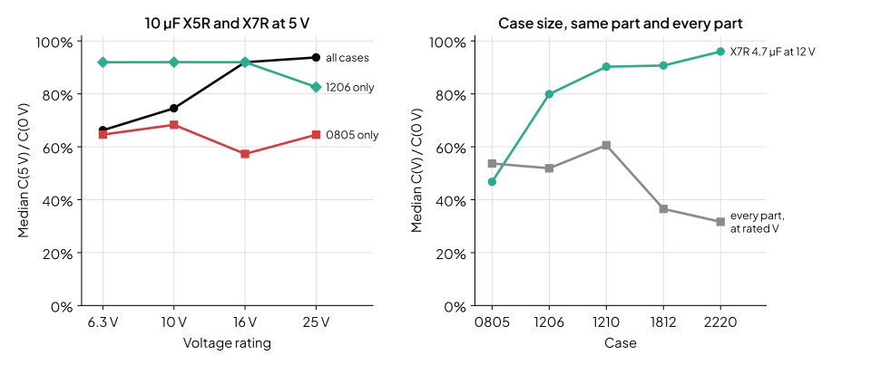
"Choose a higher voltage rating to keep capacitance." Take 10,097 pairs with the same vendor, case, dielectric and capacitance, and compare them at half the lower rating. 80% are within 5 points. 17% gain more than 5 points and 3% lose. Half the pairs have the same curve in volts to within 1%. That's the same dielectric stack, sold at two ratings. For 10 µF at 5 V, the median rises from 0.66 at a 6.3 V rating to 0.94 at 25 V. But that's only across case sizes. In 0805 it stays between 0.57 and 0.68. In 1206 it holds at 0.92 up to a 16 V rating, then falls to 0.83 at 25 V. A higher-rated part helps only when the vendor built it with thicker layers. If it's the same height in the same case, it usually doesn't. This matches Fortunato's finding that within a package and dielectric the rating "seems often to have no effect" [9].
"Choose a bigger case." Matched, this one holds. Take 4,890 pairs with the same vendor, dielectric, capacitance and rating. The larger case keeps more than 5 points more in 59% of pairs, and less in 1%. The median gain is 8 points. The catalogue reproduces the shape of Fortunato's 4.7 µF X7R table at 12 V [9], on 197 parts. The medians are 0.47 in 0805, 0.80 in 1206, 0.90 in 1210, 0.91 in 1812 and 0.96 in 2220. Across the whole catalogue the case predicts very little, because it's only one of the three things in .
"X7R loses less than X5R." Take 429 pairs with the same vendor, case, capacitance and rating. The median difference is zero. 72% of pairs are within 5 points, 17% favour X7R and 11% favour X5R. Novak's measurements found no consistent advantage either [2]. The temperature code describes the material's drift with temperature at 0 V. Under bias, the field and the density decide.
Where the numbers come from
Every curve comes from a vendor's own tool, as each vendor publishes it [5], [10], [11]. None was read off a PDF. For scale, the largest earlier multi-vendor measurement covered "more than two dozen" models from six vendors [2].
| Vendor | Tool | Class II parts | Kind of curve | Characterised parts used |
|---|---|---|---|---|
| Murata | SimSurfing | 7,907 | measured, 0.01 Vrms traces | 5,641 |
| KEMET | K-SIM | 23,181 | simulated, AC level not stated | 12,493 |
| KYOCERA AVX | SpiCAT | 3,051 | simulated, AC level not stated | 2,813 |
Left out are X8G, which is Class I in EIA terms, and 6,063 parts whose curves keep more than 99% at rated voltage. Nearly all of those (5,796) are KEMET's. They sit at a low field, where the law predicts more than 0.95 anyway. The law's constants come from the 8,453 Murata and AVX parts whose heights the catalogue holds. The ripple-level and temperature factors come from Murata alone, because only its curves state the AC level and give the bias curve at each temperature.
Murata's measurement conditions give 60 s under bias [12]. The other two tools don't say. The curves are typical, not limits, and none says how long after the last de-ageing it was taken. Under constant bias, capacitance keeps falling past 1,000 hours [13].
Assumptions and limits
- Three vendors aren't the market. Samsung, TDK, Taiyo Yuden and Yageo aren't in the data. The law's agreement across a measured and a simulated dataset suggests it's physics. It hasn't been tested on a fourth vendor.
- Two of the three datasets are simulations. K-SIM and SpiCAT are the vendors' models. The X7R constant agrees to 1% between Murata's measurements and AVX's model, which is the main evidence that the models are realistic.
- Package volume isn't active volume. Terminations, cover layers and margins take a share of it. That share varies with the case, and it's part of the error band. Murata's GR3 and GC3 series run 7 points better than the law, on average. Its reverse-geometry, low-inductance LLL series runs 6 points worse.
- Parts of 100 nF and above, 25% to 100% of rated voltage. Below 100 nF, and below a quarter of rated voltage, the loss is small. The error band wasn't measured there.
- Medians, with a spread. The ripple-level and temperature factors are medians. A single dense part can read anywhere from 0.65 to 0.86 of marked at 0 V. The worst-case design check still needs the part's own curve.
- The ripple factor is for small ripple. It's measured at 0.01 Vrms. At a few hundred millivolts, as on an input capacitor, the factor moves towards 1.
- Ageing isn't included. Class II capacitance falls with time after the part was last heated above its Curie point. It falls faster under bias. Allow for it separately, from the vendor's ageing rate.
What this means for switchmode.io
This note gets you a case and a part count before you've chosen a part, to within about 10 points on X7R. It can't tell you what each capacitor in a finished design holds at every operating corner. That takes each part's own curve, read at every corner, and switchmode.io is being built to do it. In the current alpha, its part picker already lists each ceramic capacitor at its capacitance at your design's bias. It reads that from the vendor's curve, and filters on it. So asking for "at least 20 µF at 12 V" searches Murata, KEMET and KYOCERA AVX parts together. The vendors' own tools each search one catalogue.
For what the capacitance tolerance, bias and temperature do to a control loop's phase margin, see Worst-Case Phase Margin: What Component Tolerance Does to Your Buck Converter. For a filter capacitor taken at the bus voltage, see Input Filter Damping: Sizing Rd and Cd to an Impedance Target.
References
[1] KEMET Electronics, military and high-reliability ceramic capacitor catalogue F-3113, May 2006. [Online]. Available: https://content.kemet.com/datasheets/F3113_Mil_CE_High_Rel.pdf
[2] I. Novak et al., "DC and AC bias dependence of MLCC capacitors including temperature dependence," DesignCon East, 2011. [Online]. Available: https://passive-components.eu/dc-and-ac-bias-dependence-of-mlcc-capacitors-including-temperature-dependence/
[3] R. Kalbitz, "Voltage and frequency dependence of ferroelectric class 2 multilayer ceramic capacitors," Würth Elektronik Application Note ANP114a, rev. 2, Dec. 2024. [Online]. Available: https://www.we-online.com/components/media/o753710v410%20ANP114a_Polarization%20DC%20Bias%20MLCC_EN.pdf
[4] Y. Jiang, B. Hu, Y. Shen, X. Ren, S. Sandler, S. Hofmann and T. Long, "Loss characterization and modeling of class II multilayer ceramic capacitors: a synergistic material-microstructure-device approach," IEEE Trans. Power Electron., vol. 38, no. 11, 2023. [Online]. Available: https://doi.org/10.1109/TPEL.2023.3286818
[5] Murata Manufacturing, "SimSurfing: design support software for multilayer ceramic capacitors." [Online]. Available: https://ds.murata.com/simsurfing/
[6] T. Zednicek, "High CV MLCC DC/AC bias ageing capacitance loss explained," EPCI, PCNS 2019. [Online]. Available: https://passive-components.eu/wp-content/uploads/2019/10/HIGH-CV-MLCC-DCAC-BIAS-AGEING-CAPACITANCE-LOSS-EXPLAINED.pdf
[7] I. Novak, "How much capacitance do we really get?," Signal Integrity Journal, 2017. [Online]. Available: https://www.signalintegrityjournal.com/articles/457-how-much-capacitance-do-we-really-get
[8] H. T.-J. Ma, "Diagnosing class II MLCC effective capacitance and aging under DC bias," Samsung Electro-Mechanics, Electronic Design, 2020. [Online]. Available: https://passive-components.eu/impact-of-dc-bias-to-mlcc-class-ii-dc-effective-capacitance-and-aging/
[9] M. Fortunato, "Temperature and voltage variation of ceramic capacitors, or why your 4.7µF capacitor becomes a 0.33µF capacitor," Maxim Integrated Tutorial 5527, Dec. 2012. [Online]. Available: https://www.analog.com/en/resources/technical-articles/temperature-and-voltage-variation-ceramic-capacitor.html
[10] KEMET Electronics, "K-SIM capacitor simulation tool." [Online]. Available: https://ksim3.kemet.com/capacitor-simulation
[11] KYOCERA AVX, "SpiCAT MLCC characterisation tool." [Online]. Available: https://spicat.kyocera-avx.com/mlcc
[12] Murata Manufacturing, "SimSurfing multilayer ceramic capacitors characteristics viewer: measurement conditions," Sep. 2022. [Online]. Available: https://ds.murata.com/simsurfing_data/pdf/en-us/mlcc/sim_mlcc_measuringcond_e.pdf
[13] Vishay Intertechnology, "Time-dependent capacitance drift of X7R MLCCs under exposure to a constant DC bias voltage," white paper 45263, Dec. 2021. [Online]. Available: https://www.vishay.com/docs/45263/timedepcapdrix7rmlccexptoconstdcbiasvolt.pdf