Two 48V-to-12V bus converters sit on the bench. Same efficiency, same output capacitors, same four point-of-load regulators behind them. One of them makes the rail ring. The other cannot.
Neither is better built. The difference is that one has a control loop and the other doesn't. The loop puts a peak in the source impedance, at a frequency set by its own compensator.
That is the choice at the heart of intermediate bus architecture. A regulated intermediate bus converter (IBC) holds the bus at 12V across the input range. A fixed-ratio converter, often called a DC transformer or DCX, divides whatever it's given by four and lets the bus float. The regulated part looks like the safer choice. At the interface it is the worse one, and this article quantifies by how much.
It also sets out what the fixed-ratio part costs instead, because that choice is not free either. The cost appears twice: once upstream, and once in every regulator behind it.
The interface, in one line
Two converters in series interact through the impedance they present to each other. The source presents an output impedance . The load presents an input impedance . Their ratio is the minor loop gain:
Middlebrook's criterion says keep with margin, and the cascade cannot destabilise. I derive that in Middlebrook Stability Criterion: Why Failing It Doesn't Mean Your Converter Is Unstable, and work the 48V-to-12V-to-POL cascade in Middlebrook's Criterion in Practice. This article assumes both and goes after a narrower question: what changes when the source has no loop at all.
Two converters, one impedance magnitude
Start at the 48V node, and ask what each bus converter presents to the source feeding it.
A regulated converter holds its output constant. Draw more input voltage and it draws proportionally less input current, because the power is set by the load. Its incremental input resistance is negative:
A fixed-ratio converter behaves differently. It has no loop and does not regulate its output voltage. It acts as a transformer, reflecting its load impedance scaled by the square of the turns ratio:
Those two expressions look unrelated. Evaluated at the same operating point, they are identical in magnitude:
At 48V in, 12V bus, 100W out and 96% efficient, the regulated converter presents and the fixed-ratio one . The identity is exact rather than approximate, and it holds at every power level.
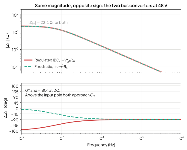
One qualification matters here, because it is where the usual account of this goes wrong. The fixed-ratio converter's input impedance is positive only because its load is. It imposes no sign of its own. Load it with regulating POLs and is itself negative, so the fixed-ratio stage presents a negative resistance too. That matters enough to have its own section below.
Why the magnitude test cannot tell them apart
Middlebrook's criterion is a test on . Feed it these two and it returns the same verdict, because the magnitudes are identical. The systems are not equally stable.
I built the case on the published cascade: a 12V bus feeding four 25W POLs at 90% efficiency, which aggregate to . Then I formed twice against the same source impedance. Once against those POLs, and once against a positive of identical magnitude.
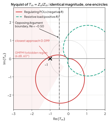
Both fail the criterion at 2.54 against a limit of 1. One is unstable and one is not.
This is the criterion being sufficient rather than necessary. It's worth knowing which way that cuts. The case Middlebrook wrongly condemns is the fixed-ratio one. A magnitude test on a DCX driving a resistive load can fail without the cascade being unstable.
The less conservative criteria differ in what they can resolve, and they do not all separate these two cases. I ran both of the ones covered in Part 1 against these two loci, at the settings quoted there:
| Criterion | Regulating POLs | Resistive load |
|---|---|---|
| Middlebrook, | FAIL at 2.54 | FAIL at 2.54 |
| GMPM, 6dB and 60° | FAIL, = 2.52 inside the wedge | FAIL, but only just |
| Opposing Argument, | FAIL at −1.799 | PASS at −0.281 |
GMPM fails both, which I did not expect. The manner of failure differs sharply, though. The negative-resistance locus sits 2.52 deep inside the wedge across 5.08 to 6.76 kHz. The positive one clips the corner: reaches 0.556 against the 0.5 boundary, over an 82 Hz span, at a phase of 120.0° to 122.8° against a 120° edge. Relax the phase margin requirement to 45° and it passes cleanly, while the negative case still fails at every setting I tried.
Opposing Argument needs no such relaxation. It constrains only the real part, and the real part is exactly where these two differ. −1.799 against −0.281, either side of the boundary, at the standard 6dB.
One caveat is worth carrying forward. Part 1's worked example came out the other way round, with Opposing Argument more restrictive than GMPM despite being the less conservative criterion on paper. The textbook ordering of conservatism does not predict which criterion binds on a given trajectory.
That is an argument for choosing the criterion deliberately, not for working through several until one returns a pass. Part 1 sets out the basis for that choice, and it is a question about the design rather than about the plot: what you are able to measure, which compliance regime you answer to, whether the input filter is permitted to alter the converter's dynamics at all, and how much the system can change after it ships. A criterion selected after the analysis, because it gives the verdict you wanted, is not a margin.
Worth being plain about what that means here. Part 1's default recommendation for a commercial design is GMPM at 6dB and 60°, and on that standard this fixed-ratio cascade is rejected. The Nyquist locus says it is stable. Both statements are true, and which one you are entitled to act on is set by the margin policy you adopted before you started, not by the plot in front of you.
What the loop costs at the bus
Now move down to the 12V bus, where the two bus converters differ for a much more practical reason.
A regulated converter's closed-loop output impedance is its open-loop impedance divided by . Below crossover the loop has gain and suppresses it. Above crossover the loop is gone and the output filter acts alone. In between, at moderate phase margin, falls below one and the loop amplifies the impedance it was fitted to reduce.
On the published cascade the minimum is 0.681, at 5.84 kHz. The loop makes the source impedance 1.47 times worse there than having no loop at all.
A fixed-ratio stage has no . Its output impedance is winding resistance, switch resistance, leakage inductance and the output capacitor. There is no frequency at which feedback makes it worse, because there is no feedback.
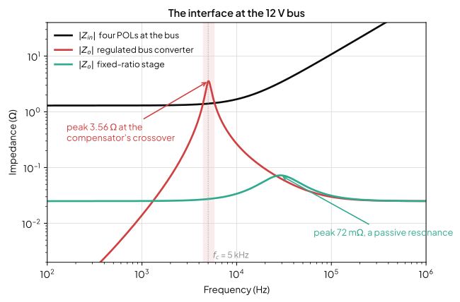
That is 3.56 Ω against 72 mΩ, a factor of 49 on the same power stage driving the same load. The regulated converter's own compensator is what puts it there.
What remains on the fixed-ratio side is an ordinary passive resonance, between the stage's leakage inductance and the bus capacitance. That is the same object as an input filter's resonance, so the damping-branch sizing in Input Filter Design: The Inductor Sets Your Stability Margin applies to it directly.
The negative resistance is relocated, not removed
This is where the usual account of fixed-ratio converters stops, and it should not.
The DCX is transparent. Put regulating POLs behind it and their negative resistance appears at its input, scaled by the turns ratio squared:
I took that as a numerical derivative rather than trusting the algebra, then checked the closed form against it. The 12V interface sees . The 48V node sees , which is times larger. The interface didn't disappear. It moved to the 48V distribution node.
What matters next is the effect on the margin. The reflection scales the whole impedance, series inductance included, so the 48V node sees in series with 261µH where the bus saw and 17µH. Every term scales by the same 15.36. The criterion is a ratio, so unless the 48V source impedance grew by the same factor, the relocated interface is the easier one.
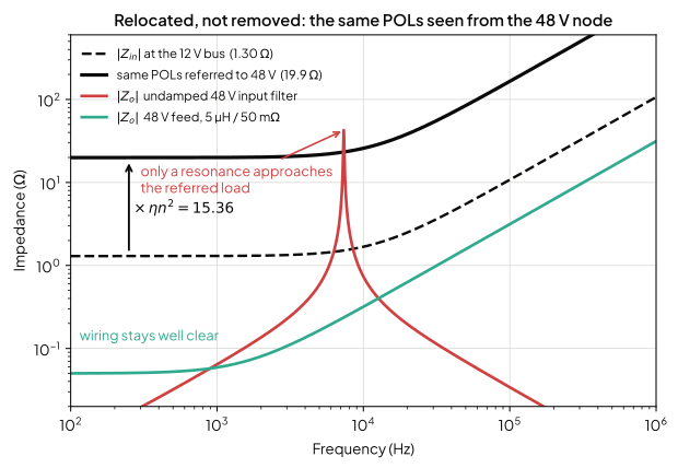
Distribution wiring cannot violate this interface. Even an implausibly long 20µH and 100mΩ run only reaches 0.077. Violating at the 48V node requires above 19.9 Ω, and distribution wiring does not reach that. A resonance does. An undamped input filter is the one element on a 48V feed that resonates. On the values above it peaks at 42.6 Ω at 7.34 kHz, and violates comfortably.
So the fixed-ratio converter does not introduce a novel problem upstream. It reintroduces the classic input-filter problem, at a node where the criterion is fifteen times more forgiving. If there is a filter on the 48V feed, damp it.
The bus voltage is the design lever
The term in the negative-resistance expression carries more weight than it first appears.
Hold the POL power constant and change only the transformer ratio. The negative resistance the bus interface has to clear scales with the square of the bus voltage:
| Ratio | Bus voltage | at the bus | at the 48V node |
|---|---|---|---|
| 2:1 | 24.0 V | 5.184 Ω | −19.91 Ω |
| 4:1 | 12.0 V | 1.296 Ω | −19.91 Ω |
| 8:1 | 6.0 V | 0.324 Ω | −19.91 Ω |
Two results follow, and the asymmetry between them is the useful one.
Downstream, halving the bus voltage makes the interface four times harder, for the same delivered power, before any component has been chosen. A 12V bus is a materially easier interface than a 6V one. That's a large part of why 4:1 and 5:1 ratios dominate the market rather than anything more aggressive.
Upstream, it's invariant. The in and the in the reflection cancel exactly, leaving . The 48V source cannot distinguish one bus voltage from another. I expected raising the distribution voltage to improve the margin at both nodes. It does not. It improves only the node upstream of the step-down.
That is the architectural argument for the whole approach: impedance scales as , so distribute at the highest practical voltage and step down as late as possible.
The cost of removing the regulation
None of the above is free. The cost appears in the POLs.
An unregulated bus converter's output is proportional to its input. The bus floats over the full input range and the regulators behind it absorb that variation. This is not a derivation. It is visible in shipping parts. Miftakhutdinov's survey of seven quarter-, eighth- and sixteenth-brick IBCs from three vendors sets it out plainly [2]:
| Type | Typical bus range | As a ratio | Efficiency | Power density |
|---|---|---|---|---|
| Unregulated (5 parts) | 6.5–11.5 V, 6.8–11.5 V, 7.1–11.0 V | mean 1.63:1 | mean 96.0% | mean 342 W/in³ |
| Regulated (2 parts) | 11.4–12.6 V, 11.0–12.5 V | mean 1.12:1 | mean 95.2% | mean 238 W/in³ |
The trade, priced from shipping parts, is about 0.8 points of efficiency and 1.44 times the power density, bought with 1.45 times the bus range. The unregulated converter achieves the higher efficiency and density because it runs at almost 100% duty at steady state, so the transformer and both filters get smaller [2].
The POL carries that cost. Its input voltage now moves nearly two to one. That means a wider duty range and a worse-conditioned loop. On a voltage-mode POL it also means a modulator gain proportional to input voltage.
There is a stability consequence as well, and it returns to the argument above. The POL's negative resistance goes as . Across vendor C's real 6.8–11.5 V unregulated bus, the aggregate moves from 0.416 Ω to 1.190 Ω — a factor of 2.86. So the Middlebrook margin at the bus interface is itself input-voltage dependent. It is worst at minimum input, where the bus sits lowest and the negative resistance is smallest.
Checking that interface at nominal input checks the easy corner. It is the same error as quoting a phase margin without stating where it was measured. The margin is a reading at an operating point, not a property of the design.
When the choice is available
The fixed-ratio stage is not a free architectural choice. It is available only when the bus is already regulated upstream, and that depends on the application.
The input ranges make the split obvious [2]. Servers and storage run 43 to 53V. Enterprise systems run 38 to 55V. Narrow telecom is 36 to 60V, and wide telecom is 36 to 75V. Push a 36-to-75V range through a fixed 4:1 ratio and the bus lands between 9 and 18.75V. Few POLs accept that range and stay efficient at both ends, so telecom retains the regulated IBC and accepts the efficiency penalty.
There is a structural answer to that constraint, and wide-range designs use it. Regulate first, then use a fixed ratio for the isolated step down. Cai and colleagues propose exactly that: a buck to 36V followed by a 1 MHz LLC running as a DC transformer [4]. The regulation still exists, but it has been moved off the interface to a point where its output impedance peak does less harm. The cost is two stages instead of one, in exchange for a clean interface.
That's also the answer to the question of why the industry "moved" from regulated to unregulated converters. It didn't. Distribution went from centralised supplies, dominant until the mid-1980s, to distributed power architecture in the early 1990s. Intermediate bus architecture continued that at the line-card level [2]. Regulation didn't follow one path through that history. It split by application, and both kinds ship today from the same vendors.
A middle option exists as well. A semi-regulated IBC uses input-voltage feedforward to hold the bus tighter than a fixed ratio would, without a full feedback loop across the isolation barrier. It costs efficiency and density against the unregulated part, because it runs over a wide duty range even at steady state [2]. Whether it helps or hurts the interface is a question I have not tested, so I will not claim an answer.
Applying this to a design
The practical summary is short.
Where a fixed-ratio stage is available, the bus interface stops being a control problem. What remains is a passive resonance, damped with a component of the designer's choosing. Check the 48V side for an input filter and damp that as well. Distribution wiring alone will not threaten that interface.
Where a regulated IBC is required, its output impedance peaks at its own crossover, and that frequency is usually fixed inside the module. Damped bulk capacitance at the interface is the available lever.
Either way, run the interface check at minimum input rather than nominal, because that's where the load's negative resistance is smallest and the margin is thinnest.
If the check fails on magnitude alone, that failure is not by itself evidence of instability. Two systems with identical can sit either side of stable, and the magnitude plot cannot distinguish them. The Nyquist locus answers the question exactly, and Part 1 recommends running it before committing hardware on a critical design. Whether you are free to act on that answer instead of on the more conservative magnitude test is a decision about tolerable risk, and it belongs before the analysis rather than after it.
The impedance curves here come from the component values quoted, using simplified closed-loop models: and with a first-order loop. They show the mechanisms rather than replacing a measurement. Doing this properly across a real system needs three things. Each converter's compensated small-signal model. The interface impedances overlaid at every corner of the input range, not at one nominal point. And the damping components carried at their worst-case values over temperature rather than their room-temperature datasheet numbers. That is exactly the analysis switchmode.io is being built to do. The overlay is where the design conversation starts. The corners are where it gets signed off.
References
[1] R. D. Middlebrook, "Input Filter Considerations in Design and Application of Switching Regulators," IEEE Industry Applications Society Annual Meeting, 1976.
[2] R. Miftakhutdinov, "Improving System Efficiency with a New Intermediate-Bus Architecture," Texas Instruments Power Supply Design Seminar, Topic 4. [Online]. Available: https://www.ti.com/download/trng/docs/seminar/Topic_4_Rais.pdf
[3] M. Panizza, "Input Source Impedance and Its Effects on DC-DC Converter Performance and Characteristics," Vicor white paper, Rev 1.0, Jan. 2022.
[4] Y. Cai, M. H. Ahmed, Q. Li and F. C. Lee, "Optimal Design of MHz LLC Converter for 48V Bus Converter Application," Center for Power Electronics Systems, Virginia Tech. [Online]. Available: https://www.osti.gov/servlets/purl/1799217
[5] P. Goff, "Avoiding Pitfalls in Unregulated Intermediate Bus Converters," Power Systems Design, May 2024. [Online]. Available: https://www.powersystemsdesign.com/articles/avoiding-pitfalls-in-unregulated-intermediate-bus-converters/159/21655
[6] R. W. Erickson and D. Maksimović, Fundamentals of Power Electronics, 3rd ed., Springer, 2020. Ch. 10 (input filter design) and Ch. 17.